Adding eurorack features to a tape recorder

One of my favorite pieces of music hardware is a 4-track TASCAM Porta 03 mkII tape recorder that I acquired back in ~2013. Having grown up with a DAW, I’d gotten the itch to record music with some self-imposed creative limitations, and a coworker at the time kindly gifted it to me (thanks Carol, if you’re out there). Though I’ve yet to use it for producing any full songs, it has found a home in my modular synth setup. I use it there to record, manipuate, and play back tape loops.
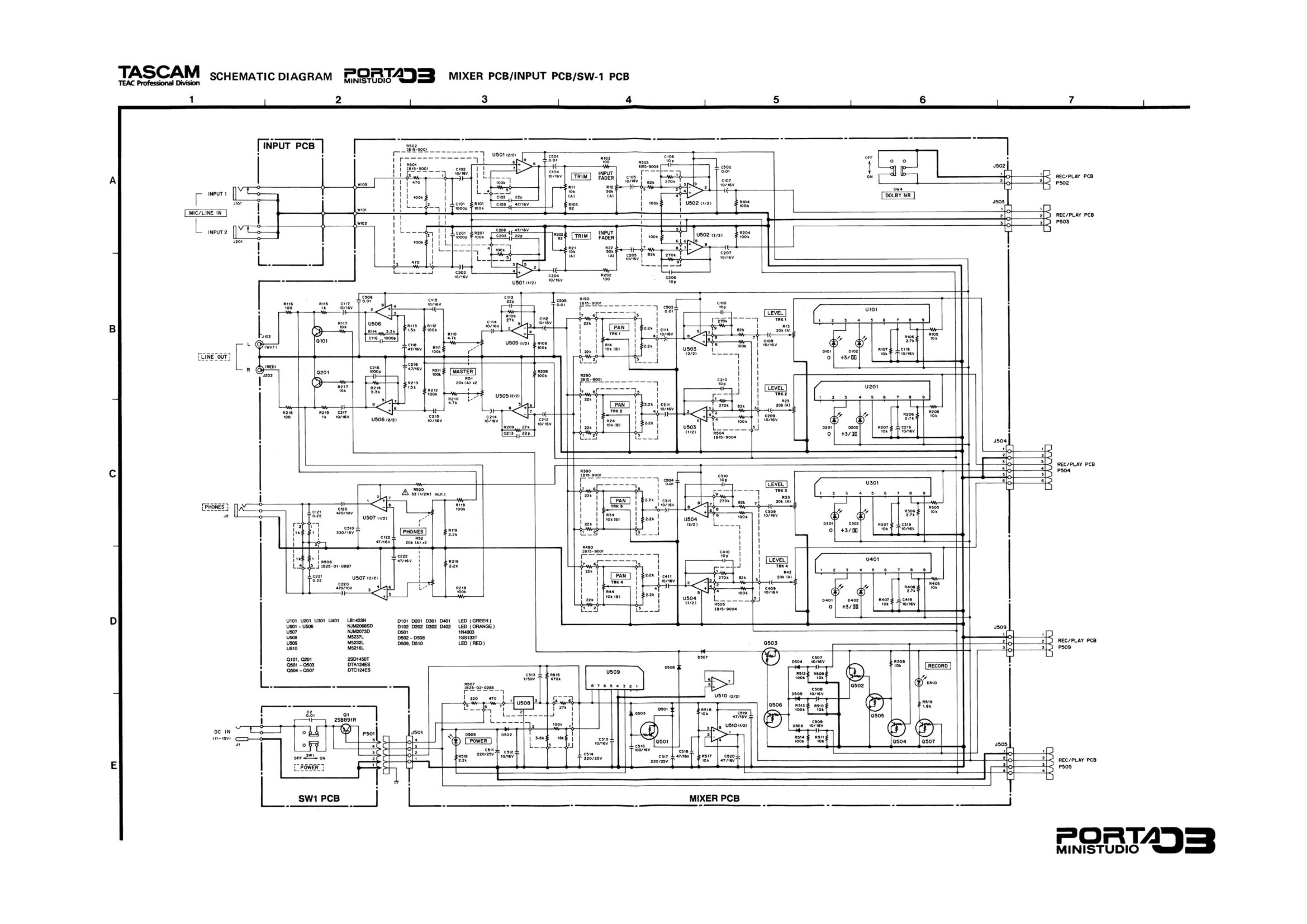
The Porta 03 has four tracks with independent level and pan controls, but only a single stereo (i.e., two channel) output. While this makes sense for its original purpose (after all, mixes typically have two channels and not four), it became a little too limiting in my modular setup since I could only route the recorded audio to at most two places. The Porta 03 was released at a time when circuits were a little simpler, and service manuals with full wiring diagrams were published. So why not hack it?

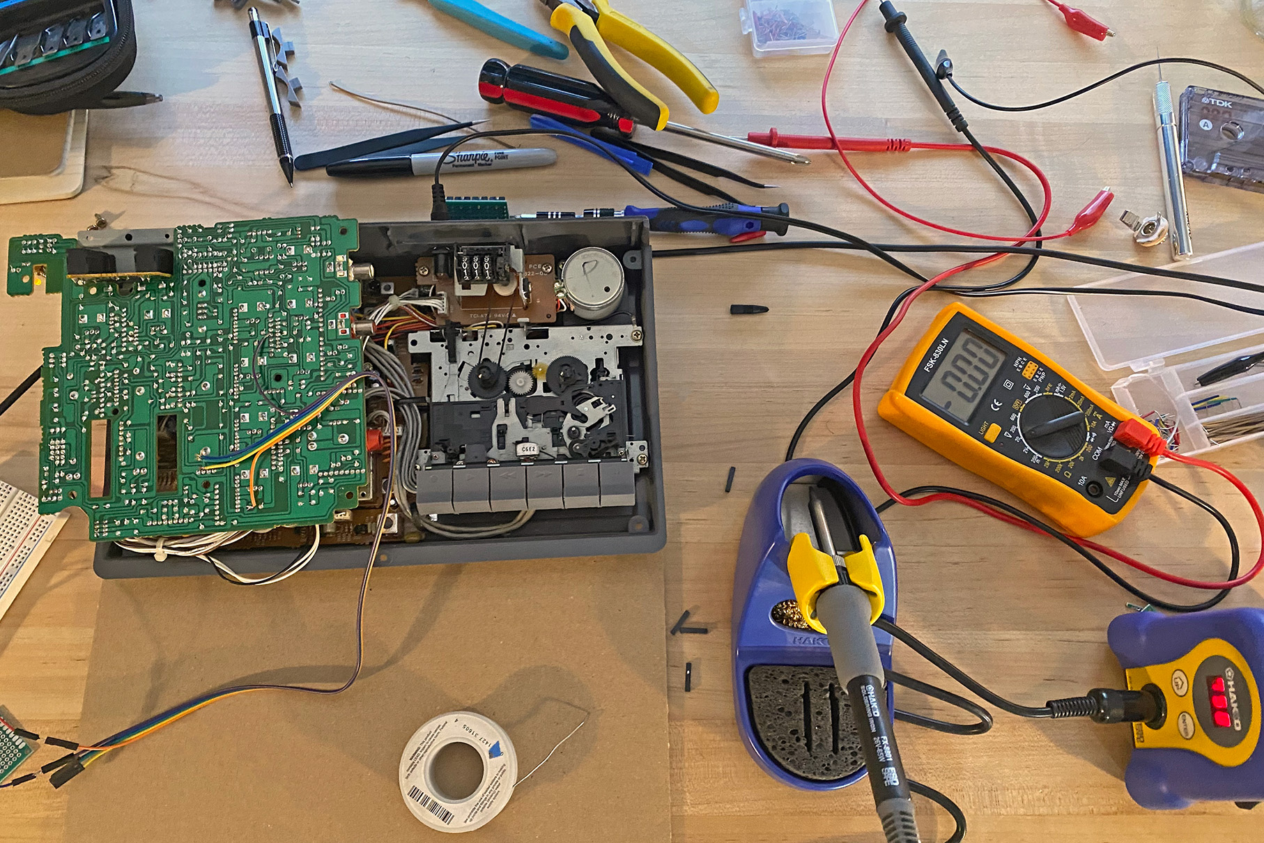
My main goal was to create a small breakout module with some 3.5mm jacks on it that could be connected to the Porta to provide added features while maintaining the ability to use the recorder standalone. The first thing I had to find was the latest point in each audio circuit prior to the mixing circuit that combines the four into a stereo output. This would allow me to use the amplifiers on each of the Porta’s audio tracks without having to make my own. After a lot of trial and error (and familiarizing myself with the schematic), I found a good spot on the Porta’s mixer PCB and soldered some jumper wires.

Having accomplished this, I figured I’d add some gates to the Porta’s audio output. This would allow me to use a gate signal from other modules to gate the audio playback of the recorder in musically interesting ways. There are many ways to create a gate, and after finding the appropriate place to tap into the Porta’s circuit to add them, I ended up going down a bit of a rabbit hole comparing the sound of two options. First, I put together a DIY vactrol gate. These work by coupling an LED and a photoresistor inside of some heat shrink tubing, and the gating effect is produced by modulating the current going into the LED (i.e., its brightness). When we vactrol gate the ambient noise of the Porta’s audio output with a sine LFO sweeping up to audio rates, this is what it sounds like:
Next, I wanted to compare this to an NPN transistor gate (specifically, a 2N3904). In this circuit, the collector of the NPN carries the audio signal, and the emitter connects to the output. The base comes from a control voltage, and when it’s held high it effectively gates the audio signal. Running the same test (again with the Porta’s ambient hiss and an LFO sweep up to audio levels), this is what the transistor-based gate sounds like:
The differences are especially apparent at the higher audio rates - the NPN is much more responsive and “digital” sounding, while the vactrol is less responsive and “warmer”. Ultimately, I went with the NPN, if only because it is more consistent and responsive than the vactrol option. With the audio outputs and gates in place and a schematic drawn, I then wired up and soldered a breakout module.

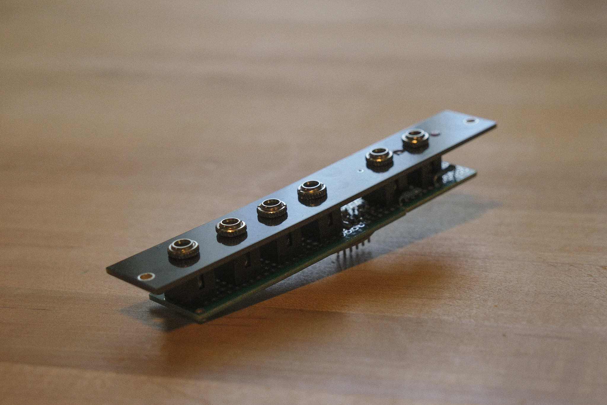
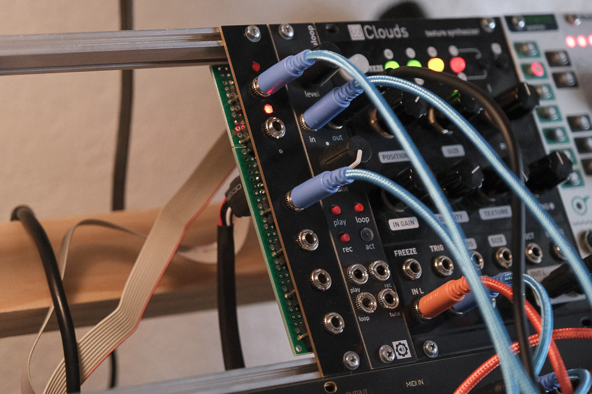
I used the classic eurorack-style Thonkiconn jacks, with the switching pin held high on the gates so that they remain open until a patch cable is plugged in. Having built the Turing Machine module some years ago, I had some flat-top LEDs lying around, which I wired to the gates to show their status. I packaged all of this up by drilling and mounting on a pre-cut fibreglass blank eurorack faceplate. To reduce the mess of jumper wires that connect the module to the Porta, I wrapped the ends in heat shrink tubing.


All-in-all, this project took about a week and definitely improved my workflow when incorporating tape loops in my patches. Thanks for reading!